What Is the Purpose of a Flexible Printed Circuit Board?
Purpose of a Flexible Printed Circuit Board
In modern electronics products, designers face contradictory requirements. They want the finished product to be light in weight, yet durable enough to survive harsh environments – heat, moisture, chemicals, shock and vibration. At the same time they need to achieve high component density and reduce manufacturing costs, all while meeting strict reliability and environmental standards. In some cases, the best solution is to use a flexible printed circuit board.
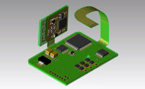
A flex circuit can solve a number of interconnect problems not addressed by traditional rigid boards. These include the ability to withstand dynamic flexing without electronic failure, and the flexibility of a 3D shape which frees up space for more product features. A flex PCB can also be easily bonded to a curved surface or formed into any 3 dimensional shape, making it ideal for connecting moving and rotating parts. Combined with a molded enclosure or other mechanical support, the flexible circuit provides interconnect for all of an electronic device’s components.
The fundamental difference between a flexible printed circuit board is that a flex has a layer of polyimide film which bonds to copper. This allows the conductive layers to be etched on both sides of the board, with precise design specifications for the circuit pattern. This gives the designer a much greater range of options for where and how to place the components of their design, which allows them to meet the needs of their end customer’s product in ways that would be impossible with a rigid board.
What Is the Purpose of a Flexible Printed Circuit Board?
As a result of the flex PCB’s polyimide base, it is also much thinner than a rigid board. This means that the traces, solder mask and other layers on the flex circuit can be made much thinner as well. This in turn, increases the density of the device population and can save space in a device package. The ability to flex also reduces the amount of material used which helps keep manufacturing costs down.
There are several basic types of flex circuits. Single-sided flex circuits are the most common. They consist of a single layer of the polyimide base material, which is then covered with a layer of pressure-sensitive adhesive (PSA) and a coverlay film. This gives the flex circuit its insulating qualities, as well as the conductors through which signals travel. Double-sided flex circuits are similar, but they have a second layer of conductive material on both sides of the polyimide base layer. This enables them to create specific trace patterns on both sides of the substrate, and they can connect through copper-plated holes.
Another type of flex circuit is the multi-layer hybrid. This uses the same construction technique as a multi-layer rigid PCB, but it adds an additional layer of FR-4 fiberglass to the mix. This acts as stiffeners at both ends of the circuit, which helps the flex circuit resist bending and deformation. The addition of this stiffener can also help to prevent the problem known as delamination, where layers break off the flex circuit.