Are Flex PCBs More Lightweight Than Rigid PCBs?
Flex PCBs More Lightweight Than Rigid PCBs
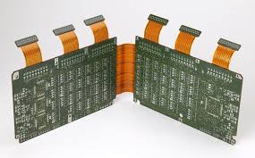
Flex PCBs are thinner and lighter than rigid boards, making them ideal for space-constrained applications. They are also much more flexible, allowing them to bend and conform to unconventional shapes and curves. Combined with their increased reliability, signal integrity, and impedance control, they can save a significant amount of mechanical space and weight in the end product.
Rigid-flex circuit boards have the added benefit of being able to eliminate connectors and cables, which can be a major source of failure in products that require repeated flexing or movement. This can reduce assembly costs and improve overall device reliability by removing points of connection that are susceptible to mechanical stress or vibrations that can lead to broken copper traces and plated-through holes (PTHs).
These benefits make rigid-flex pcbs the preferred choice in consumer, medical, automotive, industrial, and aerospace/defense electronics where space efficiency, weight reduction, and long-term reliability are important considerations. They can also replace wire harnesses in devices where equipment downtime cannot be tolerated, such as life support machines and flight control systems.
Are Flex PCBs More Lightweight Than Rigid PCBs?
Printed circuit board manufacturing is an intricate process that involves a variety of steps and equipment to create the final product. To achieve the highest quality and reliability, it is essential that a designer follow best practices and guidelines to ensure proper production. This includes adherence to Design for Manufacturability (DFM) standards, which help to identify any areas where the fabrication process may be challenged and allow designers to work with fabricators to address them.
Another important factor when designing a rigid-flex PCB is to ensure that it has adequate bend resistance. Using a rigid-flex PCB with an inadequate bend ratio can cause the copper traces to become disconnected and fail, which is a common source of reliability issues for both flexible and rigid-flex PCBs.
The thickness of the conductive layers on a flex circuit board can have a significant impact on its bend resistance. For this reason, it is critical to use a thin stack-up with the appropriate materials and layout.
In addition to ensuring that the conductive layers have adequate thickness, it is also necessary to use an appropriate dielectric material. Thicker dielectric materials increase the torsional strength of the circuit board, which helps to protect against bending and flexing.
The underlying structure of a flex circuit board is made from a copper foil that is laminated to either a thicker or thinner dielectric substrate. To protect the copper from corrosion and to increase its ductility, a heat treatment process is applied to the substrate after lamination. This annealing process helps to reduce the coefficient of thermal expansion and maintain the stability of the circuit board in temperature-controlled environments.
The final layer of a flex circuit is an epoxy-based or polyimide film. This film adds a degree of tensile strength to the circuit board and prevents damage to the traces during manufacturing and assembly processes. This allows the flex circuit to endure a variety of environmental conditions that would otherwise result in failure of rigid PCBs, including UV light, chemicals, oils, radiation exposure, and high temperatures.